
Why Choose Bevel Gears for Industrial Applications?

Industrial machinery rarely fails because of one dramatic defect. More often, small alignment errors, heat, vibration, and neglected lubrication accumulate inside a demanding drive system. Bevel Gears address one central challenge: transferring torque between intersecting shafts, often at a 90-degree angle. Their conical tooth geometry can redirect power while keeping equipment compact.

In production settings, that compactness matters. A right-angle gearbox may fit beside a conveyor, mixer, pump, or packaging line where space is limited. Properly designed Bevel Gears can deliver smooth motion, high torque capacity, and dependable speed reduction. Spiral bevel designs usually improve contact continuity and reduce noise compared with straight teeth. However, performance depends on more than the gear shape. Tooth accuracy, bearing support, housing stiffness, lubrication, and thermal control all influence service life.

Selection should begin with measured requirements, not a catalog image. Engineers need torque, speed, duty cycle, shock loads, shaft arrangement, operating temperature, and maintenance conditions. A gear that performs well in a clean factory may struggle in abrasive dust or washdown environments. Practical judgment remains important. Calculations can predict capacity, but field conditions often reveal overlooked problems. Specifications may appear adequate until starting torque or poor alignment exposes their weakness. Bevel Gears are not automatically the best choice, yet they remain a strong option when efficiency, direction change, and limited installation space must work together.
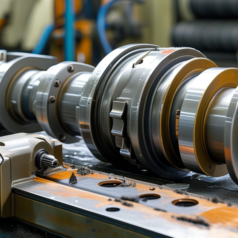
Why Choose Bevel Gears for Industrial Applications?

What Are Bevel Gears and How Do They Work?

Bevel gears are toothed wheels with cone-shaped surfaces. They transmit rotation between intersecting shafts, often at a 90-degree angle. Unlike ordinary spur gears, their teeth sit on a sloped face. This geometry changes the direction of torque inside compact machinery.

When the driving gear turns, its teeth push against the mating gear. The second shaft then rotates at a controlled speed and direction. The gear ratio depends on tooth numbers. A smaller driving gear can produce greater torque, while a larger driven gear can reduce output speed. Straight bevel gears suit simpler systems. Spiral bevel gears usually provide quieter, smoother engagement under heavier loads.

In industrial equipment, these gears appear in conveyors, machine tools, lifting systems, and right-angle drives. Their performance depends on accurate shaft alignment, suitable lubrication, and correct backlash. Too little clearance may cause heat and tooth damage. Too much can create vibration and uneven wear. Heat is a warning.

From practical maintenance work, inspection should include tooth contact patterns, housing temperature, noise, and lubricant condition. A clean contact mark often indicates good alignment. However, that check is not perfect. Loads can change during operation, and installation errors may remain hidden at low speed. Bevel gears are powerful, but their reliability comes from careful design, precise assembly, and regular inspection.


How Bevel Gears Transfer Motion Between Intersecting Shafts

Bevel gears transfer motion between shafts that meet at an angle, commonly 90 degrees. Their toothed, cone-shaped surfaces change the direction of rotation while carrying torque through the gearbox. As one gear turns, its teeth push against the mating gear along intersecting pitch cones. The result is controlled angular motion, not simply a change in speed.

In industrial equipment, straight bevel gears suit moderate speeds and simpler mechanisms. Spiral bevel gears usually operate more quietly because their curved teeth engage gradually. However, that smoother contact can increase axial forces and heat. Engineers must check shaft alignment, tooth contact, backlash, and bearing capacity before selecting a design.

During maintenance, uneven tooth marks often reveal poor alignment or insufficient lubrication. A thin oil film matters. Without it, friction can quickly damage the tooth flanks. Correct mounting also prevents vibration, especially when shafts carry changing loads. Gear geometry determines the speed ratio, while material hardness affects service life and resistance to pitting.

Bevel gears are not perfect. They may produce noise, thrust loads, and efficiency losses when installation is careless. In practice, a compact design can still fail if the housing flexes under load. Engineers should evaluate operating temperature, shock loads, lubrication access, and expected duty cycles rather than rely on nominal torque alone. Small details matter.

Why Choose Bevel Gears for Industrial Applications?

How Bevel Gears Transfer Motion Between Intersecting Shafts

This chart illustrates the ideal relationship between bevel-gear ratio, output speed, and output torque when the input speed is 1,500 rpm and the input torque is 100 N·m. Increasing the reduction ratio lowers output speed while proportionally increasing theoretical torque, allowing bevel gears to redirect motion between intersecting shafts while adapting speed and force for industrial machinery. Actual performance is lower because of friction, sliding, and manufacturing tolerances.

Which Bevel Gear Types Suit Industrial Machinery?

Bevel gear selection starts with shaft layout, speed, load, and maintenance conditions. Straight bevel gears suit compact, low-to-moderate speed machinery. Their simple tooth geometry reduces manufacturing cost and simplifies inspection. However, they can produce noticeable noise at higher speeds. Spiral bevel gears offer smoother engagement and stronger load distribution. They fit pumps, conveyors, mixers, and automated production equipment requiring continuous operation.

Hypoid gears work well when shafts need an offset arrangement and higher reduction. Their sliding contact can improve quietness, but it also increases heat and lubrication demands. Zerol bevel gears provide a practical middle option. They reduce some noise without creating the same axial thrust as strongly angled spiral teeth. Selection should follow calculated loads, not catalog habit. ISO 23509 defines bevel gear geometry, while AGMA rating practices assess bending strength and surface durability.

Efficiency deserves attention. The U.S. Department of Energy reports that motor-driven systems consume roughly 60% of electricity in U.S. manufacturing. IEA’s Energy Efficiency 2023 report places industry near 37% of global final energy consumption. A small transmission loss can therefore become a large operating cost. In field maintenance reviews, misalignment often causes more failures than tooth design. That detail is easy to miss. Engineers should check backlash, bearing support, lubricant viscosity, contamination control, and thermal rise together. A high-capacity spiral bevel gear can still fail early when its housing flexes under load. The specification may look correct, but the installation reality can disagree.

What Benefits Make Bevel Gears Ideal for Industry?

Bevel gears are valuable when industrial machinery must transfer power between intersecting shafts. Their angled teeth can redirect rotation, often at 90 degrees. This layout helps engineers fit drives into compact equipment frames. Space matters. In factories, smaller gear arrangements can simplify machine access and reduce structural modifications.

Their biggest benefit is controlled torque transmission. Properly designed bevel gears distribute loads across matched tooth surfaces. This supports smooth motion in conveyors, pumps, mixers, and material-handling systems. They can also maintain dependable performance under changing loads. In practical maintenance work, technicians often notice reduced vibration after correcting shaft alignment and backlash. That detail is easy to overlook.

Bevel gears also offer design flexibility. Straight, spiral, and other tooth forms suit different speed, noise, and load requirements. Spiral forms generally operate more quietly and handle contact gradually. They may require more careful lubrication and inspection. Nothing is automatic. Poor installation can create heat, tooth wear, and unexpected noise. Engineers should evaluate speed, torque, operating temperature, housing space, and service access before selecting a gear set. A compact design may look efficient, yet become difficult to repair. That tradeoff deserves honest attention. Regular checks of lubrication, mounting bolts, tooth surfaces, and bearing condition help preserve reliable operation over time.

What Factors Guide Bevel Gear Selection and Maintenance?

Why Choose Bevel Gears for Industrial Applications?

What Factors Guide Bevel Gear Selection and Maintenance?

Bevel gears suit machinery that needs torque transmission between intersecting shafts. Their angled teeth can redirect power through compact assemblies. Selection should begin with torque, speed, ratio, shaft angle, and operating hours. A conveyor running continuously needs different specifications than a short-cycle packaging machine. Fit matters. Check the housing space, shaft diameter, mounting direction, and expected shock loads. Helical bevel gears often operate more quietly, while straight bevel gears may offer simpler, economical designs. The choice depends on noise limits, efficiency targets, and service conditions.

Maintenance begins with correct alignment and suitable lubrication. Even a strong gear set can fail when shafts are offset by a small amount. Inspect tooth contact patterns during commissioning and after major repairs. Uneven wear, pitting, or bright edges can indicate overload or poor adjustment. Measure backlash according to the equipment maker’s technical requirements. Keep records. Include temperature, vibration, lubricant condition, and inspection dates. A rising gearbox temperature near a bearing can reveal trouble before visible damage appears. Seals also deserve attention, especially in dusty workshops or washdown areas.

In field maintenance, I have seen premature failures blamed on gear quality when loose foundations caused the real problem. That assumption is easy, but incomplete. Selection calculations should include starting torque, reversing loads, duty cycles, and ambient temperature. Maintenance intervals may need adjustment after real operating data becomes available. A design that looks perfect on paper may require refinement after installation. Review it honestly. This practical feedback improves reliability without replacing sound engineering judgment.

Why Choose Bevel Gears for Industrial Applications? - What Factors Guide Bevel Gear Selection and Maintenance?

Evaluation Dimension Typical Options or Reference Values Why It Matters in Industrial Applications Selection or Maintenance Guidance
Primary Function Transmit torque between intersecting shafts and change the direction of rotation, commonly by 90°. Bevel gears provide a compact right-angle drive for machinery where parallel-shaft gearing is unsuitable. Confirm shaft angle, output direction, speed ratio, torque, and available installation space before choosing the gear geometry.
Gear Type Straight bevel, spiral bevel, zerol bevel, or hypoid gear. Straight teeth are simple and economical; spiral teeth generally provide smoother, quieter engagement and higher load-carrying potential. Hypoid gears allow shaft offsets but introduce sliding action. Use straight bevel gears for lower-speed or cost-sensitive duties; consider spiral or hypoid designs where smoothness, compactness, or higher performance is required.
Transmission Ratio The ratio is determined by the tooth-count relationship between the mating gears; a single stage is commonly used for moderate ratio changes. A larger ratio change affects output speed, transmitted torque, tooth loading, and physical gear size. Calculate the required output speed and torque, then verify that the selected ratio does not exceed the gear manufacturer’s recommended limits.
Torque and Power Determine continuous torque, peak or starting torque, operating speed, duty cycle, and service factor from the actual machine load. Insufficient rating can cause tooth bending, pitting, scuffing, shaft damage, or premature bearing failure. Include shock loads, frequent starts and stops, reversing, overloads, and cyclic operation in the rating calculation rather than using nominal motor power alone.
Speed and Operating Duty Low, medium, or high rotational speed; continuous, intermittent, or severe cyclic duty. Higher speed increases heat generation, lubrication demands, noise sensitivity, and the consequences of imbalance or misalignment. Check allowable pitch-line speed, thermal capacity, dynamic balance, bearing speed limits, and the manufacturer’s duty-cycle assumptions.
Material and Heat Treatment Common choices include case-hardened alloy steel, through-hardened steel, cast iron, and selected nonmetallic materials for light-duty applications. Material and hardness influence wear resistance, bending strength, impact resistance, noise, and service life. Match hardness and toughness to the load spectrum, shock level, lubrication system, corrosion exposure, and required operating life.
Accuracy and Backlash Gear accuracy and backlash should be specified according to the required positioning precision, speed, noise level, and thermal conditions. Tight control supports smoother motion and positioning, while excessive backlash can cause impact, vibration, and lost motion. Do not minimize backlash without considering thermal expansion, lubrication film thickness, assembly tolerances, and the risk of tooth interference.
Noise and Vibration Spiral tooth forms, accurate machining, correct contact pattern, and proper alignment generally reduce operating noise and vibration. Low vibration improves operator comfort, product quality, bearing life, and the reliability of connected equipment. Investigate sudden changes in sound or vibration; they may indicate wear, incorrect tooth contact, looseness, imbalance, or inadequate lubrication.
Lubrication Oil-bath, splash, circulating-oil, or grease lubrication, depending on speed, enclosure design, temperature, and load. Lubricant forms a protective film, removes heat, limits wear, and helps prevent corrosion and scuffing. Use the specified viscosity and lubricant type; maintain the correct level, prevent contamination, and change lubricant according to condition or operating schedule.
Alignment and Mounting Accurate shaft alignment, rigid housing support, correct bearing installation, and controlled gear backlash. Misalignment concentrates load on part of the tooth face and can accelerate wear, noise, heat, and tooth failure. Follow assembly tolerances, inspect contact patterns, verify shaft runout, tighten fasteners correctly, and recheck alignment after major maintenance.
Temperature and Environment Consider ambient temperature, enclosure temperature, dust, water, chemicals, humidity, washdown, and corrosive atmospheres. Heat reduces lubricant viscosity and material margin; contaminants can damage tooth surfaces and bearings. Select suitable seals, coatings, housing protection, lubricant, and cooling arrangements. Monitor abnormal temperature increases.
Inspection Indicators Pitting, scoring, scuffing, wear, tooth fracture, discoloration, backlash change, metal particles, noise, and vibration. These signs can reveal lubrication failure, overload, contamination, misalignment, fatigue, or poor contact before a major breakdown. Record inspection findings over time and compare them with baseline temperature, vibration, sound, backlash, and lubricant condition.
Maintenance Interval Intervals depend on speed, load, duty cycle, lubricant, environment, and operating temperature rather than on calendar time alone. Condition-based maintenance can identify deterioration earlier and reduce unnecessary component replacement. Establish routine visual, lubricant, temperature, vibration, and backlash checks, and use the equipment manual for formal service intervals.
Application Suitability Suitable examples include conveyors, pumps, mixers, packaging machinery, material-handling systems, machine tools, and industrial drives. Bevel gears are valuable when a compact, rigid, right-angle transmission is needed with dependable torque transfer. For every application, verify load spectrum, duty cycle, efficiency, noise limits, environmental conditions, service access, and expected life before final selection.

Note: Actual ratings, permissible speeds, lubrication requirements, and service intervals must be confirmed against the gear set’s engineering documentation and the complete operating conditions.

Start WhatsApp Chat Start WhatsApp Chat
Valves

Valves

Water Meters

MS Forged Pipe Fittings

Fittings

Water Meters

Valves

DI Grooved Fittings (UL/FM)

Water Meters

DI Screwed Fittings (UL/FM)

Fittings

Composite Pipes & Fittings

Site Credits : Seigospace