How to Choose the Right Pipe Fittings and Valves
Choosing the right fittings valves is not a catalog exercise; it is a decision about how a complete system will behave under real operating conditions. A fitting that seals perfectly on a cool water line may fail when temperature rises or the fluid changes. A valve with the right connection size may still restrict flow or prove awkward to maintain. Small details matter.
For this guide, fictional composite process engineer Alex Morgan offers an illustrative principle, not a verified quotation: “Match every fitting and valve to the fluid, pressure, temperature, and maintenance plan—not just the pipe size.” That is a practical starting point, not a substitute for checking manufacturer specifications. Compare connection types, body and seal materials, pressure ratings, operating temperatures, and compatibility with the conveyed fluid. Then consider the task: ball valves often suit quick isolation, while other designs may offer better control or different flow characteristics. Pressure changes everything. A compact layout can also make inspection or replacement difficult; I have seen that kind of oversight turn a simple service job into a frustrating one.
The strongest selection process uses system data, product documentation, and input from qualified engineers or suppliers. Confirm the operating and peak conditions, not just normal readings. Check how the valve will be actuated, how often it will cycle, and whether the fitting can be accessed safely. No shortcut works. Even careful choices deserve a second review, because site conditions and assumptions can differ. This outline explains how to compare options, spot common mismatches, and choose fittings valves with performance and maintainability in mind.
Define Design Pressure, Temperature, Fluid, and Flow Requirements
A fitting or valve should be selected from actual service conditions, not pipe diameter alone. Record design pressure and temperature, including credible startup, shutdown, and upset cases. A hot-water line may see a pressure spike when a pump starts. Small details matter. Use the project design basis, and do not mistake normal operating readings for maximum conditions. Check pressure and temperature ratings together; a component suitable for one may not be suitable for both.
Describe the fluid precisely: composition, phase, solids, viscosity, and corrosivity can all affect material and trim choices. Define a flow range rather than one target value. Note minimum and maximum flow, expected pressure drop, and whether the valve must control or isolate. An oversized control valve may hunt at low flow, while an undersized one can restrict capacity. Keep assumptions visible. A tidy datasheet can still miss a cleaning fluid used only occasionally. Would the selected seal tolerate it? Check connection type, end loads, and installation space against the piping layout, then seek qualified engineering review for unusual or severe service.
Select Fitting Geometry: ASME B16.9 Covers NPS ½–48 Butt-Weld Fittings
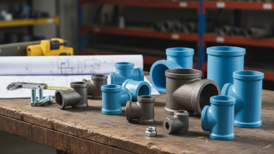
Choosing fitting geometry starts with the pipe route, not the catalog picture. ASME B16.9 covers factory-made wrought butt-welding fittings from NPS ½ through NPS 48 (ASME B16.9, Scope). That range includes elbows, tees, reducers, and caps, but it does not mean every size is readily available. NPS is a nominal designation, not the pipe’s measured outside diameter. Check the project’s pipe schedule and drawings before matching components.
Geometry affects fit-up and flow. A long-radius elbow may suit a gradual direction change, while a short-radius elbow can help where space is tight. Reducers need careful orientation: an eccentric reducer installed the wrong way can create an unwanted pocket in a horizontal line. Small detail. It matters. ASME B16.25 addresses butt-welding end preparations, so confirm bevel requirements alongside B16.9 dimensions. The two references answer different questions.
I would not treat the standard’s size range as a buying guarantee. Verify material, wall thickness, end preparation, and dimensional tolerances against the actual piping specification. ASME B16.9 sets fitting dimensions and tolerances; it does not replace project pressure-design checks. A quick drawing review can catch mismatched ends before welding begins. One detail is easy to miss: fitting geometry must work with valves, supports, and maintenance access, not just connect two pipe ends.
ASME B16.9 Butt-Weld Fitting Size Range
ASME B16.9 covers factory-made wrought butt-welding fittings from NPS ½ to NPS 48. The bars show selected nominal pipe size designations within that range, not measured outside diameters.
Use the applicable standard tables and project specifications to confirm fitting dimensions and selection requirements.
Choose Materials by Corrosion Exposure, Temperature, and ASTM/ASME Grade
Choosing pipe fittings and valves begins with the fluid, not the catalog. Identify its chemistry, concentration, and temperature, then check for contaminants such as chlorides. A stainless fitting may suit clean water but pit in warm, chloride-rich service. Carbon steel can be practical in dry, controlled systems, yet wet outdoor exposure may demand coating or a different alloy. Small details matter: a damp support, trapped condensate, or dissimilar metal joint can become the first failure point.
Temperature changes the decision. Heat can reduce allowable pressure and accelerate corrosion; repeated heating and cooling can also stress joints. Check the full operating range, including startup and cleaning conditions. ASTM material specifications identify requirements for components such as pipe, fittings, and valve bodies. ASME standards address matters such as pressure ratings, dimensions, and design rules. These are related, but not interchangeable. Confirm the exact specification, grade, class, and service limits in the project documents. Names can look similar. They may not mean the same thing.
Match the fitting and valve materials to the same exposure, and review seals and trim as well. A corrosion-resistant body with an incompatible stem or gasket is not a durable assembly. For uncertain water chemistry, obtain test data rather than guessing from appearance. That step can feel slow. It is often cheaper than replacing a valve after a season. I would still revisit assumptions when conditions change; a material choice that worked in one line may fail in another.
Size the Valve and Check Its ASME B16.34 Pressure–Temperature Rating
A valve that matches the pipe’s nominal size may still be poorly sized for the service. Check the required flow, pressure drop, and operating range before selecting its bore or flow coefficient. For example, a DN50 line carrying a small, steady flow may need a different valve opening than one handling rapid changes. Oversizing can make control erratic; undersizing can restrict flow. Small details matter. Note the fluid, expected flow rate, and any startup or shutdown conditions.
Then verify the valve’s ASME B16.34 pressure–temperature rating for its material group and pressure class. The listed rating changes with temperature, so a valve acceptable at ambient conditions may not be suitable at the design temperature. Compare the rating with the maximum design pressure at that temperature, not just the normal operating pressure. Account for credible pressure surges, too. Do not guess. Check the applicable table and confirm the valve’s construction and end connection meet the project specification. It is easy to focus on the class number alone; that can miss material and temperature limits. When conditions fall near a rating boundary, ask a qualified piping engineer to review the selection before purchase.
Match Flange Connections: ASME B16.5 Covers NPS ½–24 and Classes 150–2500
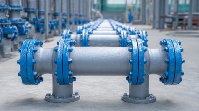
When selecting pipe fittings and valves, match the flange standard, nominal pipe size, pressure class, facing, and material—not just the bolt pattern. ASME B16.5-2020 covers flanges and flanged fittings from NPS ½ through NPS 24. Its pressure classes include 150, 300, 400, 600, 900, 1500, and 2500. Small detail. The class number is not a universal pressure rating in psi.
ASME B16.5 provides dimensional requirements and pressure-temperature ratings, which vary by material group and operating temperature. Check the applicable tables for the selected material and conditions, then confirm the valve flange matches the mating pipe flange. A Class 150 flange at elevated temperature may have a lower allowable pressure than at ambient conditions. That detail is easy to overlook on a drawing. Also verify the facing type, gasket arrangement, and bolt dimensions before installation; similar-looking flanges may not seal or align correctly. ASME’s standard is the primary reference, but project specifications and the equipment manufacturer’s certified data should also be reviewed. I would not assume a match from NPS alone.
How to Choose the Right Pipe Fittings and Valves - Match Flange Connections: ASME B16.5 Covers NPS ½–24 and Classes 150–2500
| Selection Dimension |
What to Match |
Practical Check |
| Standard and scope |
ASME B16.5 covers pipe flanges and flanged fittings in NPS ½ through NPS 24, with Class designations 150, 300, 400, 600, 900, 1500, and 2500. |
Confirm the applicable edition and verify that the selected size and Class combination is covered by the standard. |
| Nominal pipe size (NPS) |
Match the flange NPS to the connected pipe, fitting, or valve end. |
NPS is a nominal size, not a direct measurement of pipe outside diameter. Check the component drawings and applicable pipe dimensions. |
| Pressure Class |
Use the same Class designation on mating flanges and flanged equipment connections. |
Class numbers are not pressure ratings in psi. Allowable pressure depends on material group and temperature; consult the standard’s pressure-temperature tables. |
| Flange facing |
Match the facing type and facing dimensions, such as Raised Face (RF), Flat Face (FF), or Ring-Type Joint (RTJ). |
Do not assume different facing types can be bolted together safely. Check the equipment requirements and connection design. |
| Gasket |
Select a gasket that suits the facing, fluid, pressure, temperature, and flange finish. |
For RTJ connections, confirm the ring style and dimensions match the groove. Use the project specification to determine gasket material and type. |
| Bolt pattern and fasteners |
Verify bolt-hole number, diameter, and bolt-circle dimensions, along with the required bolt and nut sizes. |
Matching NPS and Class alone is not sufficient if the drilling or fastener requirements differ. Follow the applicable standard and installation specification. |
| Material and service conditions |
Check flange, fitting, and valve materials against the fluid, corrosion conditions, design pressure, and operating temperature. |
Confirm material compatibility and pressure-temperature suitability. A matching Class marking does not by itself establish suitability for a particular service. |
| Valve or fitting end connection |
Match the component’s flange size, Class, facing, and drilling to the adjoining piping flange. |
Check the component’s dimensional drawing and connection details before ordering or assembly. |