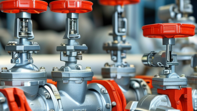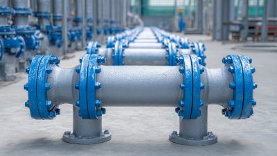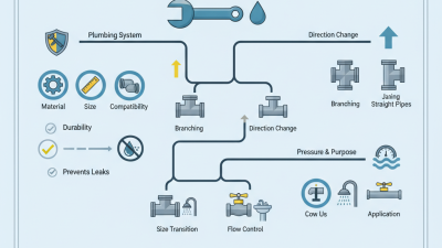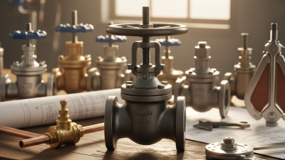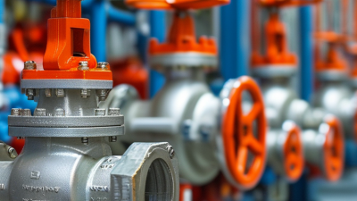
Pipes do not work alone. They need connections that guide flow, change direction, control pressure, and allow maintenance. Pipe fittings valves cover a wide range of components, from elbows and tees to gate, ball, globe, and check valves. Each type serves a specific purpose. An elbow turns a line around a corner; a tee creates a branch; a ball valve can shut off flow with a quarter-turn handle. Small details matter. A fitting that looks right may still have the wrong thread, size, or pressure rating.
This guide explains common pipe fittings and valve types, how they work, and where they are typically used. It also outlines key choices, including material, connection method, fluid compatibility, operating temperature, and system pressure. These details help readers compare options for plumbing, irrigation, industrial lines, and other applications. A real installation may be less tidy than a diagram. Existing pipe conditions, limited access, or unclear markings can complicate selection, so specifications should be checked rather than guessed. Not every system follows the same rules. Understanding the basic differences is a practical starting point for choosing components that fit the line and its operating needs.
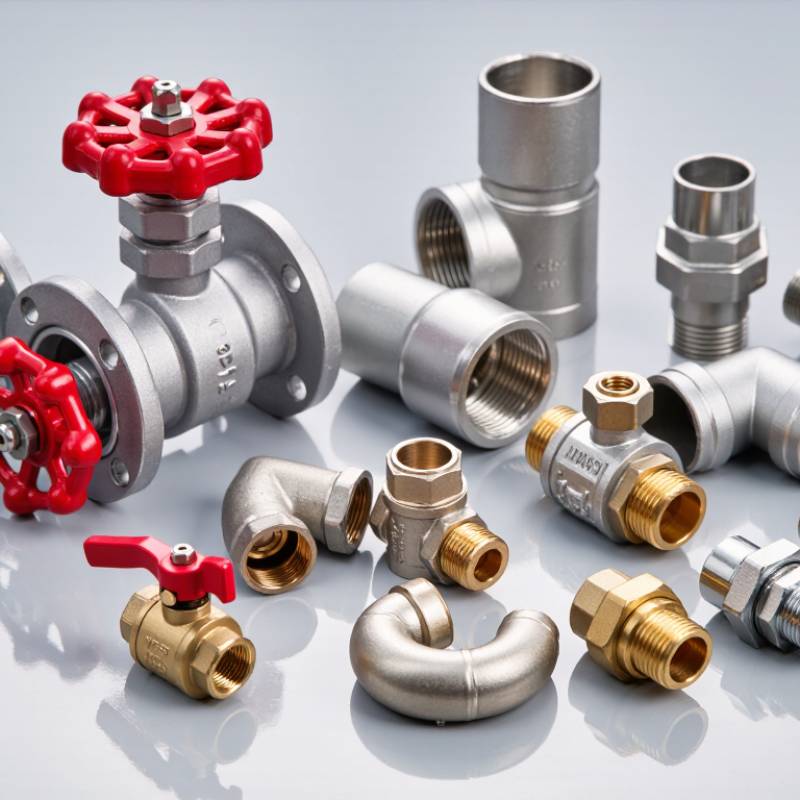
Pipe fittings and valves perform different jobs, even when they sit side by side. Fittings connect pipe sections, change direction, branch a line, or adapt its diameter. Elbows turn flow around corners, tees create branches, and reducers join pipes of different sizes. A coupling may reconnect a short cut section. These parts shape the route, but they do not normally regulate flow.
Valves control, stop, or redirect what moves through the pipe. A ball valve opens or closes with a quarter-turn handle; a gate valve lifts a barrier from the flow path. Check valves help prevent reverse flow. The distinction sounds simple, yet it can blur during a rushed repair. A fitting that looks right may still mismatch the pipe material, connection type, or pressure rating. Small differences matter.
Tips: Before installation, check the system’s working pressure, temperature, fluid compatibility, and connection dimensions. Confirm the valve’s flow direction where marked, especially for check valves. Leave enough clearance to turn handles and service joints. If specifications are unclear, pause and verify them; guessing is rarely a good fit.
| Component Group | Type | Main Function | Typical Flow or Routing Effect | Common Connection or Use |
|---|---|---|---|---|
| Pipe Fitting | Elbow | Changes the direction of a pipe run. | Routes flow around a corner; commonly available in 45° and 90° angles. | Joined by threaded, welded, socket, or other system-compatible connections. |
| Pipe Fitting | Tee | Connects a branch pipe to a main pipe. | Splits flow into a branch or combines streams, depending on the system layout. | Has three openings; equal and reducing versions are common. |
| Pipe Fitting | Reducer | Connects pipes of different diameters. | Changes pipe size and can affect flow velocity and pressure loss. | Concentric and eccentric designs are used for different layout requirements. |
| Pipe Fitting | Coupling | Joins two pipe ends, usually in a straight run. | Maintains the route of the pipe without providing an operating flow-control function. | May be threaded, socket-type, or designed for another specified joining method. |
| Pipe Fitting | Union | Joins two pipe sections while allowing later disconnection. | Provides a removable joint for maintenance or equipment replacement. | Often used where a pipe section may need to be dismantled. |
| Pipe Fitting | Flange | Creates a bolted connection between pipes, equipment, or other components. | Does not normally regulate flow; allows a joint to be separated for inspection or maintenance. | Used with a gasket and bolts; flange standards and ratings must match the system. |
| Valve | Gate Valve | Starts or stops flow using a movable gate. | Typically intended for fully open or fully closed service, rather than frequent throttling. | Common in applications where low flow resistance when fully open is useful. |
| Valve | Globe Valve | Controls or throttles flow with a movable plug and seat. | Well suited to flow adjustment, though it generally creates more pressure loss than a full-bore open valve. | Used where flow regulation or frequent adjustment is required. |
| Valve | Ball Valve | Opens or shuts flow using a rotating ball with a bore. | Quarter-turn operation; many designs provide quick shutoff. | Available in different port sizes and connection styles; suitability depends on service conditions. |
| Valve | Butterfly Valve | Controls or isolates flow with a rotating disc. | Quarter-turn operation; the disc remains in the flow path when open. | Often used on larger-diameter lines where a compact valve design is useful. |
| Valve | Check Valve | Allows flow in the intended direction and limits reverse flow. | Operates automatically in response to flow or pressure conditions; it is not normally a manual shutoff valve. | Installed in the correct orientation for the design and expected flow direction. |
| Valve | Plug Valve | Opens or shuts flow using a rotating plug with a passage through it. | Often provides quarter-turn operation for on/off service. | Designs and sealing arrangements vary; selection depends on fluid and operating conditions. |
| Valve | Diaphragm Valve | Uses a flexible diaphragm to control flow and separate the mechanism from the fluid. | Can provide shutoff and, in suitable designs, flow regulation. | Used where the fluid-handling design benefits from a barrier between the process fluid and operating parts. |
| Valve | Pressure-Relief Valve | Opens when pressure reaches a set condition to protect a system from overpressure. | Releases fluid or gas as designed, then reseats according to its operating characteristics. | Must be selected and installed for the protected equipment, pressure, and applicable requirements. |
| Key Difference | Fittings vs. Valves | Fittings connect, branch, redirect, or change the size of piping; valves control, isolate, or regulate flow. | Fittings generally establish the piping layout, while valves provide an operating function within that layout. | Both must be compatible with the fluid, pressure, temperature, pipe size, material, and joining method. |